
STCrushers Is A Professional Minging Equipment Manufacturer since 2004, Providing High Quality Crushers, Sand Making Machines, Drying Equipment and more.
STCrushers Is A Professional Minging Equipment Manufacturer since 2004, Providing High Quality Crushers, Sand Making Machines, Drying Equipment and more.
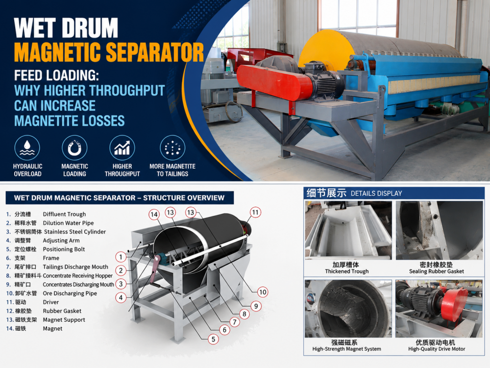
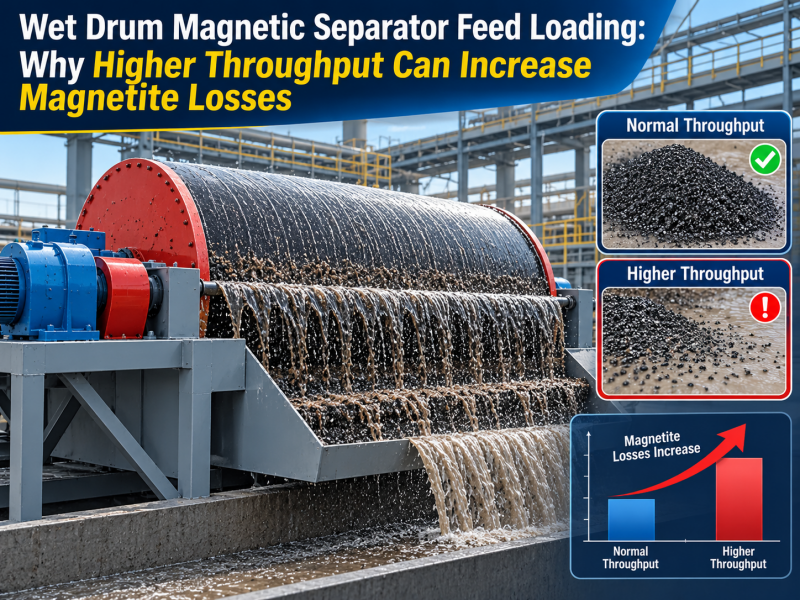
A wet drum magnetic separator may appear to accept a higher feed rate without mechanical trouble. The drum keeps rotating, concentrate continues to discharge, and the tank does not visibly overflow.
However, tailings samples may show more magnetite after the feed pump is accelerated or the solids rate is increased. Concentrate discharge may also become thicker, less even across the drum width, or more variable during the shift.
This article concerns wet low-intensity drum separation of strongly magnetic minerals such as magnetite. Weakly magnetic ores may require different equipment. Rated throughput should not be treated as one fixed dry-tonnage number because the separator handles both slurry flow and magnetic solids.
Wet drum sizing has two separate loading questions. Hydraulic loading is the volume of slurry passing through the tank and separation zone. Magnetic loading is the mass of magnetic material that must be captured, transported on the drum surface, and discharged.
A separator can reach either limit first. A dilute slurry may create high hydraulic flow even when dry solids are moderate. A feed with a high magnetite percentage may create heavy magnetic loading before the tank reaches its maximum slurry volume.
This is why two plants processing the same dry ore tonnage can require different drum width, number of stages, or operating rate.
Inside the tank, magnetic attraction acts against hydrodynamic drag. Water movement helps wash non-magnetic particles away, but the same drag can also carry magnetic particles toward the tailings stream.
When slurry flow rises, velocity through the separation area generally increases. Fine magnetite, partially liberated particles, and particles entering an unfavorable flow path have less opportunity to remain attached to the drum. The result can be higher magnetic loss even though field strength and drum speed have not changed.
Adding more water is therefore not an automatic correction for a dense feed. It may reduce solids concentration while increasing total slurry volume and hydraulic loading.
Dry feed capacity does not show how much magnetic material the drum must remove. A 50 tph feed containing a relatively small magnetic fraction creates a different duty from 50 tph of magnetite-rich feed.
As magnetic loading rises, more material occupies the active drum surface. The separator must collect the particles, hold them against slurry drag, transport them out of the tank, and release them at the concentrate discharge.
When the magnetic layer becomes too heavy for the available drum width and operating condition, outer particles can be less securely retained. Non-magnetic particles may also become physically trapped in the concentrate, so recovery and grade can deteriorate in different ways.
Total flow can look acceptable while part of the drum is locally overloaded. A feedbox that sends most slurry to the center or one side leaves some magnetic width underused and forces another area to handle excessive flow and magnetic solids.
Inspect the feedbox level, distribution plates, blocked passages, tank level, and the concentrate layer across the full width. Uneven discharge is often a useful warning that the average flow number is hiding a distribution problem.
A separator may handle a stable rate but lose performance during short surges. Pump cycling, unstable classifier overflow, sump-level control, or irregular mill discharge can create peaks that are much higher than the recorded hourly average.
During a surge, slurry velocity and magnetic loading rise together. The separator may recover normally before and after the event while more magnetite is lost during the peak.
Buffering and steady upstream control may improve performance without changing the separator model.
A very high solids concentration increases particle crowding and competition in the magnetic field. Gangue can become physically trapped in the magnetic product, while some magnetic particles may not reach a favorable collection position.
A very low concentration can increase the slurry volume required to deliver the same dry solids rate. This raises hydraulic loading and may reduce practical plant capacity.
The useful operating concentration is therefore process-specific. It should remain stable and be evaluated together with particle size, magnetic fraction, tank style, water balance, and the duty of the stage.
Increasing drum speed may move concentrate away faster, but it also changes residence and transport conditions. Increasing field strength may capture more composite particles or gangue when liberation is poor. Neither adjustment corrects an overloaded feedbox or excessive slurry velocity.
The separator also has a defined process duty. A rougher prioritizes recovery, while a cleaner must reject more non-magnetic material and protect concentrate grade. Settings that appear helpful at one stage may be unsuitable at another.
Observed change | Possible effect | First check |
Slurry flow increases | Higher velocity and hydrodynamic drag | Pump rate, tank level, and slurry volume |
Magnetic fraction increases | Higher magnetic loading per unit drum width | Feed magnetic content and dry solids rate |
Feed enters one side | Local overload and unused drum width | Feedbox, distribution plate, and blockages |
Solids concentration fluctuates | Changing hydraulic load and selectivity | Classifier overflow, water addition, and sump control |
Tailings magnetics rise after a capacity increase | Practical loading limit may be exceeded | Return to the baseline rate and compare samples |
Concentrate layer becomes uneven | Poor distribution or discharge condition | Full drum width, scraper, lip, and feed entry |
Grade drops while recovery appears high | More non-magnetics may be entrained | Loading, liberation, concentration, and cleaning duty |
The practical limit should be found through controlled sampling rather than one rapid production increase.
1. Stabilize feed particle size, slurry concentration, and upstream classification.
2. Record a baseline dry solids rate, slurry flow, magnetic fraction, drum speed, and tank condition.
3. Take representative feed, concentrate, and tailings samples at the baseline.
4. Increase the feed in small steps and allow the circuit to stabilize after each change.
5. Compare magnetite loss, concentrate grade, and discharge uniformity across the drum width.
6. Record short surges instead of relying only on hourly average flow.
7. Stop increasing the rate when tailings loss, grade, tank stability, or discharge behavior begins to deteriorate.
8. Confirm that the selected operating point remains stable across normal ore variability.
No universal flow, concentration, or magnetic-loading value should be copied from another separator without checking drum diameter, width, magnetic circuit, tank style, particle size, and application. Equipment-specific limits and test data should control the final setting.
1. Ore type and magnetic response.
2. Feed particle-size distribution and liberation condition.
3. Required dry ore capacity per hour.
4. Slurry flow rate and solids concentration.
5. Percentage or mass rate of magnetic material in the feed.
6. Target recovery and concentrate grade.
7. Roughing, cleaning, scavenging, or media-recovery duty.
8. Upstream ball mill, classifier, pump, and sump arrangement.
9. Current tailings and concentrate sample results.
10. Available water, recycled-water condition, and expected feed variability.
A wet drum magnetic separator is not at useful capacity simply because slurry continues to pass through it. The operating rate must also maintain acceptable magnetite recovery, concentrate quality, tank level, and discharge stability.
Hydraulic loading and magnetic loading should be checked separately. Feed distribution, surge control, solids concentration, particle liberation, and stage duty then determine how close the separator can operate to its practical limit.
Sentai Machinery can review ore data, feed size, slurry flow, magnetic fraction, capacity target, tailings results, and the upstream grinding and classification circuit before recommending a magnetic separator or process adjustment. Samples and operating records provide a stronger basis than a dry-tonnage request alone.
1. Why Is Magnetic Separator Recovery Lower Than Expected
2. Iron Ore Processing Plant Design: Confirm Ore Type Before Choosing the Process Route
3. What Buyers Often Miss When Matching a Ball Mill and Spiral Classifier
4. Why Crushing Size Before Ball Milling Affects Grinding Cost
5. Ball Mill vs Rod Mill: How to Choose the Right Grinding Stage for Mineral Processing
2. Ball Mill

 WhatsApp
 Email
Email
 +86 15538010601